
Global Site
Displaying present location in the site.
Outline of Disaster Recovery Architecture
Vol.1, No.4 November 2006, Special Issue: Business Continuity and Disaster RecoveryThis paper discusses aspects of IT systems from their basic architectures to a function model of the disaster recovery (DR) that enables continued service provision even in the case of a disaster event. In doing so it focuses on data protection, which is the core of service continuity.
1. Introduction
The purpose of disaster recovery (DR) is to make an IT system capable of continuing service provision even in the case of a disaster event and also to protect its data. This paper describes the basic concept of developing the DR systems and Solutions and the DR architecture. The core content of the preparation of DR architecture lies in protecting data in order to ensure service continuity. Therefore, this paper also describes general data protection techniques by comparing them at the functional level.
2. DR Concept
With regard to the basic ideas related to DR, we will first discuss the elements required for continuous service provision, the basic concepts of the elements from the viewpoint of DR and the service levels implemented by DR.
A service features software as one of its integral part as well as the data to be utilized by that software. In addition it also requires other infrastructure elements such as the server running the software and storages for storing data, as well as other facilities such as suitable locations for installing the infrastructures. Of these, the software, infrastructures and facilities can be retrieved after the disaster, but it is extremely difficult to retrieve data once it has been lost. Therefore, the minimum requirement for continuing to provide a service after a disaster is to protect any data that may be exposed to a disaster event.
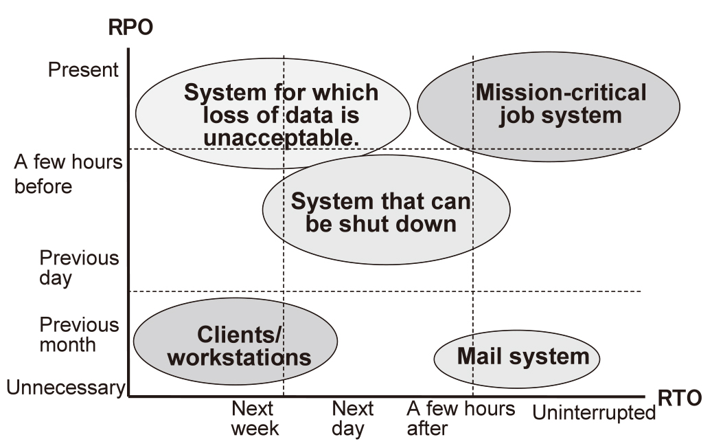
DR employs the RPO (Recovery Point Objective) and RTO (Recovery Time Objective) as its standards. RPO represents the level of data protected at the moment of service recovery, and RTO represents the time required before service recovery is achieved.
DR first considers the necessary level of RPO, which is determined depending on the data protection method. Next, DR considers RTO, which is determined on the degree of preparation of the backup site to be used in restarting the service after a disaster event. In addition, the operations administration provides an important contribution to the continued provision of all of these factors.
The RPO and RTO requirements vary depending on the systems adopted as shown in the examples in Fig. 1. This example assigns the mail system with an RTO level of zero and an RPO of “Month,” but this practice is because the design emphasizes the operation of the system rather than the retention of data. The RPO level will naturally be much shorter in the case of jobs for which the retention of mail data is critical.
3. Architecture
Let us now review the basic DR architecture by taking as an example the 3-layer model used as the information system of a general enterprise. The 3-layer model system is composed of the three layers: Access, Service and Data. Fig. 2(a) shows a DR system architecture based on such a 3-layer model. In this figure, the left side represents the main site of service that is usually provided and the right side represents the backup site that inherits service provision in the case of the main site being affected by a disaster event. DR needs to be explicitly aware of the location (geographical) and facility (building, electricity, air conditioning, etc.,) which are hardly detected by conventional systems. The two sites are connected via the data protection layer. When the main site is affected by a disaster event, the backup site resumes the service. In such a case it is the recovery layer that executes the required processing.
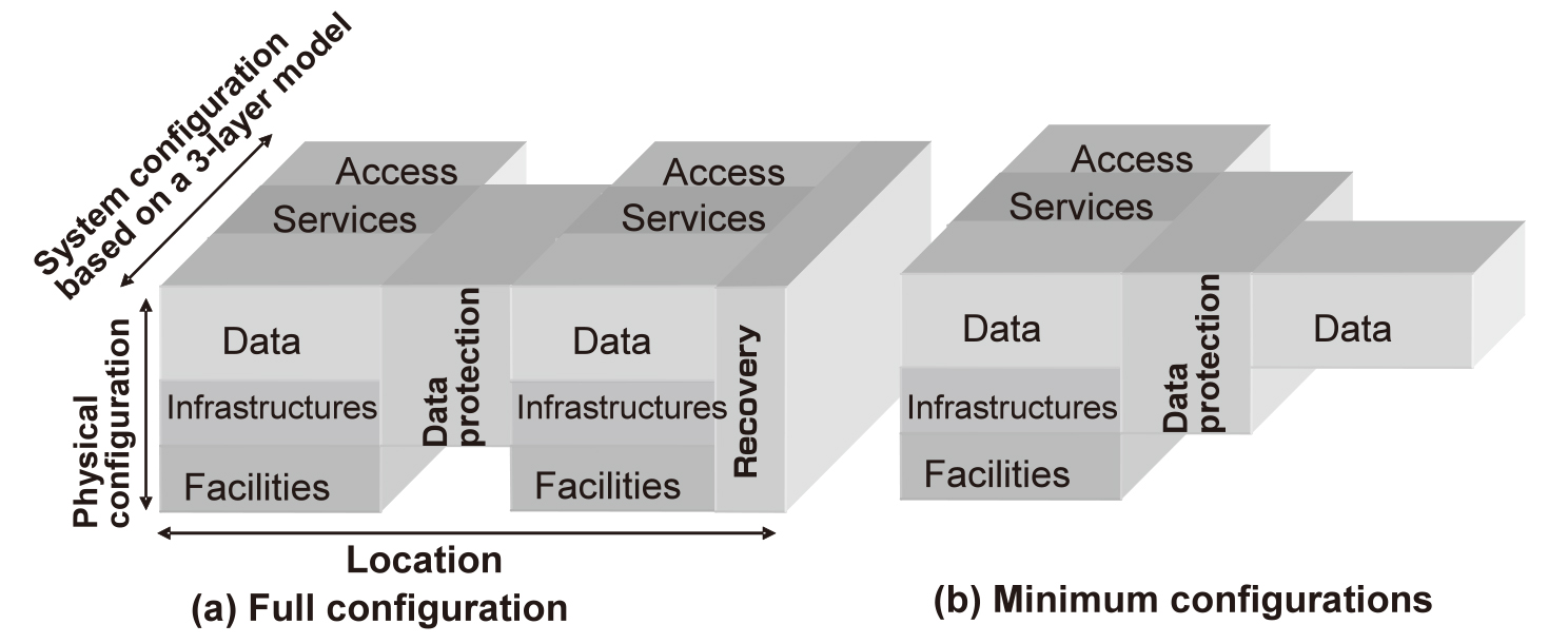
Fig. 2 Architectures for service continuity.
Arranging the DR architecture in this way makes it possible to offer proposals matching the needs of customers. For example, if a configuration as shown in Fig. 2(a) is prepared in advance, it becomes possible to recover the service with a short RTO. It is also possible to protect only the data in advance of the event, as shown in Fig. 2(b). In this case, it is necessary to reserve the facilities and prepare the infrastructures and software after the disaster event occurs.
4. Function Model
Next, let us examine a function model by using an architecture that is closer to the actual system. The following description will be limited to the data protection that should be prepared in advance for enabling DR.
Fig. 3 illustrates a function model. Note that this figure shows only those layers of the architecture referred to in Section 3 above that are associated with data protection, including the services, data, data protection and recovery layers.
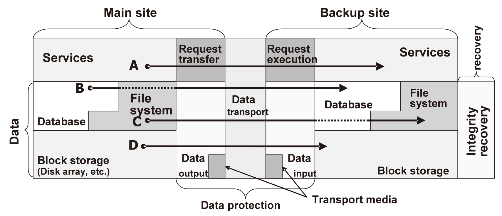
Fig. 3 Function model (Data duplication path).
The data layer can be separated into three elements, which include the database, the file systems, and the block storages for eventual data storage, such as in a disk drive or disk array. Each file system is either a local system inside the server or an appliance-based system such as an NAS.
The data protection layer is composed of the section that outputs data from the main site, the section that transports data from the main site to the backup site, and the section that receives data into the backup site. The data is transported either by sending it through the network or recording it in a portable medium such as a data tape and transporting physically.
When the data protection is in question, the main objective of the recovery layer is to recover the integrity of the data in the databases and file systems.
A service can access data in the block storage by direct access using the database, by passing through the file system at the same time as using the database, or by using the file system.
Data protection is achieved by duplicating the data from the main site into the backup site. The data duplication methods include the method executed by the service (A in Fig. 3), by the database (B in Fig. 3), by the file system (C in Fig. 3) or that executed by the block storage (D in Fig. 3). Data can be duplicated either synchronously, in which case processing is awaited in the period when data changes are transmitted to the backup site, or asynchronously, in which case changes in data are reflected at any given point in time from the main site to the backup site.
Arranging the function model related to data protection makes it possible to propose a data protection technique that matches the system being used by each customer.
5. Characteristics of Data Protection Techniques
As the data protection techniques described above can be provided respectively at different levels, it is essential to understand the characteristics of each data protection technique. The Table below shows the comparison between data duplication methods. It evaluates the seriousness of the problem with each item using the symbols ◎ (No problem), 〇 (minor problem), △ (Slightly problematic) and × (Problematic). For the method of executing data duplication in the service layer, the Table deals only with the synchronous technique.
Table Comparison of data protection techniques.
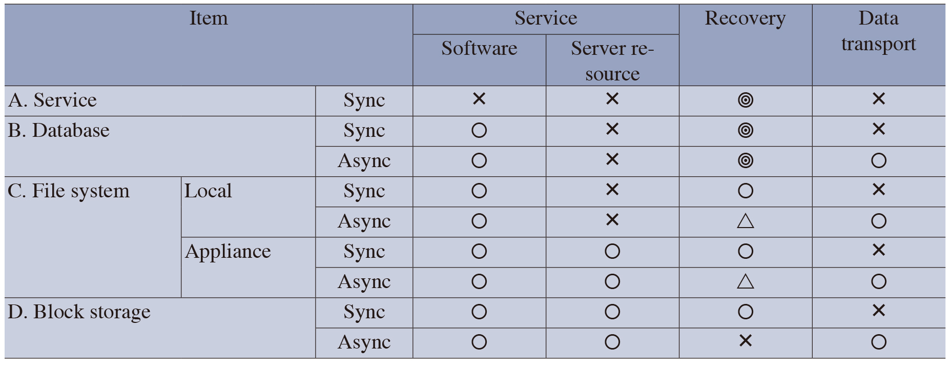
For the items in the Table the comparisons in “Software” focuses on whether or not the software should be modified, and the case in which modification is required is marked “ד. In this case, the problem is that, to execute duplication in the service layer, the software should be modified and the duplication function should be incorporated when modifying the software. The comparisons in “Server Resource,” focuses on whether or not the CPU resource of the server is used up. In the duplication process and that in “Recovery” focuses on whether or not the service recovery may be easily achieved. Although the asynchronous technique using the block storage is evaluated as “ד, a recovery is still possible by obtaining the quiescent point after data integrity is obtained and by transferring the data at the quiescent point. Note that the level of seriousness of a problem depends on the actually used products and the operations administration method. The comparison in “Data transport” is focused on the effects of the response property, limitation in distance and the need for a high bandwidth in the communication circuit.
6. Conclusion
In the above, we summarized the concept of DR, its architecture and a function model for the data protection that forms the basis of DR. For the data protection function model, we also compared possible data protection techniques. Although the discussion in this paper remained at the summary level, the ideas described in it form the basis of various solutions offered by NEC. We intend to offer optimum DR solutions for each customer based on these ideas.
Authors’ Profiles
YAMATO Jun-ichi
Assistant Manager,
System Platforms Research Laboratories, NEC Corporation
Member of the Information Processing Society of Japan (IPSJ) and the Institute of Electronics, Information and Communication Engineers (IEICE).
Assistant Manager,
System Platforms Research Laboratories, NEC Corporation
Member of the Information Processing Society of Japan (IPSJ) and the Institute of Electronics, Information and Communication Engineers (IEICE).
KAN Masaki
Researcher,
System Platforms Research Laboratories, NEC Corporation
Member of the Information Processing Society of Japan (IPSJ).
Researcher,
System Platforms Research Laboratories, NEC Corporation
Member of the Information Processing Society of Japan (IPSJ).
KIKUCHI Yoshihide
Assistant Manager
System Platforms Research Laboratories,
NEC Corporation
Assistant Manager
System Platforms Research Laboratories,
NEC Corporation
TAKAYA Masahiro
Group Manager,
IT Platform Systems Development Division,
NEC Corporation
Group Manager,
IT Platform Systems Development Division,
NEC Corporation
TOMI Mitsuhiro
Manager,
IT Platform Division,
NEC System Technologies, Ltd.
Manager,
IT Platform Division,
NEC System Technologies, Ltd.
ADACHI Tadashi
Assistant Manager,
New Solutions Development Division,
NEC Corporation
Assistant Manager,
New Solutions Development Division,
NEC Corporation