Global Site
Displaying present location in the site.
Comprehensive Digital Predistortion for improving Nonlinear Affection and Transceivers Calibration to Maximize Spatial Multiplexing Performance in Massive MIMO with Sub6 GHz Band Active Antenna System
Vol.17 No.1 September 2023 Special Issue on Open Network Technologies — Network Technologies and Advanced Solutions at the Heart of an Open and Green Society PDF
PDFNEC has pursued spatial multiplexing performance with Massive MIMO by adopting full digital beamforming (BF) that can realize high spectrum efficiency in the commercial Sub6 GHz (less than 6GHz) band Massive Element Active Antenna System (AAS) for domestic and overseas 5G. Through NEC’S R&D activity, it has been found that Downlink (DL) SINR (Signal to Interference and Noise Ratio) to each user terminal (UT) deteriorated by the nonlinear distorted radiation caused by the power amplifier (PA) in transmitter (TX). Thus, NEC has confirmed that the use of Digital Predistortion (DPD) significantly improves DL SINR in high power region. And it has been also verified that the accuracy of nulls generated in each user terminal direction is determined by the residual amplitude and phase variation among all transceivers after calibration (CAL). Thus it was clarified that the double compensation of DPD and high-precision CAL is effective for achieving excellent spatial multiplexing performance by Massive MIMO.
1. Introduction
As opposed to the millimeter-wave system in 5G, in the case of Sub6 GHz frequency range, it is not easy to secure the wide frequency bandwidth, but Sub6 GHz system shall be essential as the true 5G mobile usage because of its wide area coverage characteristics including non-line-of-sight propagation effect. Taking these factors into consideration, it is effective in realizing superior spatial multiplexing (Massive MIMO) by Sub6 GHz band AAS with full digital BF to secure high spectrum efficiency in narrow low frequency band1)2).
Therefore, NEC has mainly developed the commercial Sub6 GHz band AAS with full digital BF and DPD to avoid nonlinear affection caused by TX PAs. And by implementing transceivers CAL in addition to the above functionalities, it was confirmed that the spatial multiplexing performance was significantly improved up to the high DL output power with the wide dynamic range3)4).
After improving the DL SINR by suppressing nonlinear distorted radiation to the same BF direction with DPD, or when using in the low DL output power region with high linearity, DL/UL (Uplink) CAL accuracy, which determines the depth of nulls to the direction of other UTs formed on the DL radiation pattern for each UT, is dominant in determining the DL SINR, so DL/UL CAL to match the amplitude and phase frequency characteristics of the on-board multiple Transmitters (TXs) and Receivers (RXs) is also important.
In this way, NEC has developed the commercial AASs that can realize excellent spatial multiplexing performance over the wide dynamic range in output power by adopting double compensation scheme of DPD and DL CAL for AAS3).
In this paper, in order to mainly focus on the influence of nonlinear distorted radiation on DL SINR, multiple user’s signals are radiated in anechoic chamber, and the opposite reception signal is demodulated or spectrum analyzed to obtain DL SINR. And S/I angular spectrum was calculated by S/I separation (“S”: Desired wave, “I”: OFDM/Multitone distortion component). By calculating this S/I radiation pattern, the peculiarity of the nonlinear distorted radiation “I” was confirmed.
2. Section
2.1 Features of Sub6 GHz band AAS with DPD used for the verification
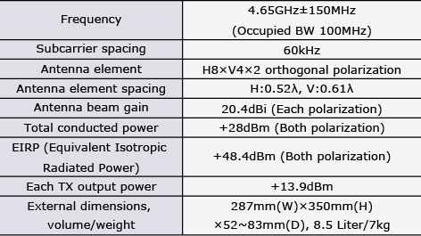
Fig. 1 shows the block diagram of the AAS used for the verification, and Photo shows the external view of AAS (the photo shows the operation when 2AAS are connected horizontally), and Table shows the specifications of AAS. The antenna element is composed of ± 45 ° dual polarization shared patch antenna, and is equipped with total 64 antenna elements with horizontal 8 x vertical 4 x 2 polarization configuration. As the number of TXs and receivers (RXs), 32 transceivers (TRXs) with horizontal 8 x 2 sets of vertical 2 antenna grouping x 2 polarization are integrally mounted on the back side of the antenna by connecting 2 vertical antenna elements with each polarization to 1 TRX.
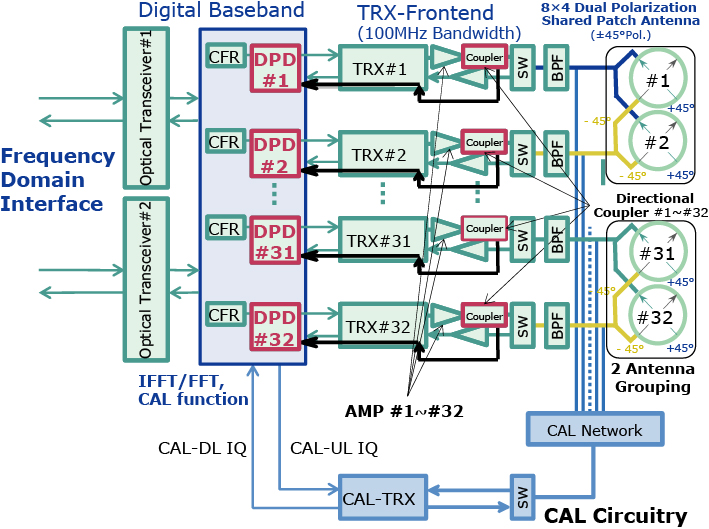

Table AAS specifications.
The DPD is individually mounted in the digital baseband section of each transmitter, and nonlinear distortion compensation is performed by extracting PA output with nonlinearity using a directional coupler and returning it to each DPD processor. And the Generalized Memory Polynomial (GMP) method was adopted as the DPD in order to realize optimum nonlinear distortion compensation, and also to reduce circuit scale.
Furthermore, in order to secure spatial multiplexing performance in TDD (Time Division Duplex) system, Zero-Forcing precoding is applied to generate DL BF weight to each UT with deep nulls in the other UT directions by using UL channel estimation from each UT. And UL channel estimation is carried out by SRS (Sounding Reference Signal) receptions from each UT to all RXs in AAS, and DL channel matrix can be approximated by UL channel estimation in case of TDD).
And in order to ensure DL/UL reciprocity in TDD, DL/UL CAL shall be necessary to match multiple TXs/RXs magnitude and phase frequency characteristics
2.2 Maintaining stability of radiation pattern including nulls with DPD-equipped AAS by applying calibration
In order to confirm the normality of CAL when DPD is activated in combination, the amplitude and phase variations between all 32 transmitters were actually measured while automatically updating the DL CAL compensation weight for each TX every 90 seconds.
As a representative example, Fig. 2 (above figure) shows the results of actual measurement of the phase fluctuations of all 32 transmitters over a period of 3 hours. It was confirmed that the phase variation was very stable within ±4°.
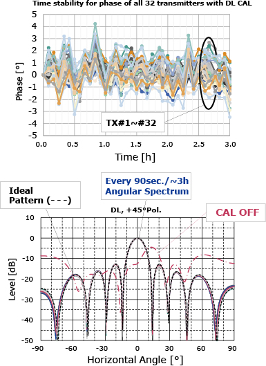
Furthermore, in Fig. 2 (below figure), DL sounding was iterated sequentially with performing DL CAL in the anechoic chamber by every 90 seconds, and the DL angular spectrum was obtained from DL channel estimation resulted by DL sounding. Due to the phase stability shown in Fig. 2 (above figure), it was also confirmed that a stable beam and null could be maintained for 3 hours3).
2.3 Verification for the specificity of nonlinear distorted radiation generated under single layer beam radiation in the high output power region
With the Sub6 GHz band AAS equipped with DPD, the OFDM signal is firstly radiated to the front direction in the anechoic chamber when the nonlinear distortion compensation by DPD is On and Off respectively.
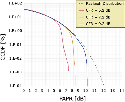
In this analysis, as shown by CCDF (Complementary Cumulative Distribution Function) of PAPR (Peak to Average Power Ratio) in Fig. 3, by limiting the peak power level 5.2 dB/7.2 dB/9.2 dB higher than the maximum output power level (1 TX output level:+13.9 dBm, total conducted output level:+25 dBm) by CFR (Crest Factor Reduction), a pseudo -nonlinear characteristic is set in the AAS so that the peak power of the OFDM signal passing through each TX system is intentionally clipped. The saturation level of TX exists above the maximum output power + 9.2 dB.
The output level dependency of DL SINR measured in the anechoic chamber is summarized in Fig. 4, by converting the received RF signal with opposite side cross polarization antenna to the I/Q baseband signals and performing demodulation analysis.
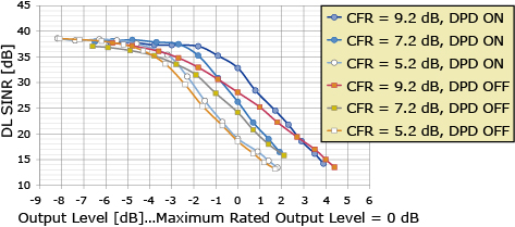
Due to Fig. 4, it was clarified that DPD On case can improve the amplitude and phase linearity of each TX until a remarkable nonlinear distortion occurs in the peak clipping defined in each CFR setting.
In this experiment, by radiating a single layer beam to the front direction of AAS, the angular spectrum of desired signal “S” was obtained by taking the cross-correlation between TX signal in AAS and the received signal by opposite side cross polarization antenna. Furthermore, by subtracting the desired signal “S” from the total received signal of each horizontal angle, the interference signal “I”, which is mainly determined by the nonlinear distortion in high output power region, was separated and the angular spectrum of the nonlinear distorted radiation “I” was obtained.
As a result, Fig. 5 shows the S/I angular spectrum obtained for each of the CFR settings of 5.2 dB/7.2 dB/9.2 dB in DPD On. In Fig. 6, it was confirmed that the component “I” was emitted in the same direction as the desired radiation “S”5).
2.4 Verification for the specificity of nonlinear distorted radiation generated under multi-layer beam radiation in the high output power region
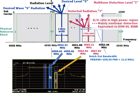
Furthermore, in order to clarify the nonlinear distorted radiation specificity under the spatial multiplex with multiple layer in the high output power region, the NPR (Noise Power Ratio) method shown in Fig. 6 was applied6)7).
And Notch Out Band by the several subcarriers turned off was set in all bandwidth as 125 Physical Resource Blocks (PRB, 4.55 GHz ± 45 MHz).
Moreover, when multiple layer beams are generated as the desired wave “S” (95 PRB) outside of the Notch Out Band (30 PRB of 21.6 MHz from 4561.88 MHz to 4583.48 MHz), the horizontal radiation characteristics as the spatially multiplexed “S” (0 ° for 1 layer, 0 ° and -20 ° for 2 layers, 0 °, -20 °, + 20 ° and -40 ° for 4 layers) and the distorted component “I” that falls into the Notch Out Band were measured by spectrum analyzer set up at the opposite side of AAS in the anechoic chamber.
The “S” and “I” radiation levels were individually measured in each 5 MHz bandwidth, and DL SINR was derived by the ratio between “S” and “I” levels. And the peak power limitation was fixed as CFR setting of 9.2 dB.
As shown in Fig. 7 in which the PAPR of each of the multiple layer signals is represented by CCDF, as with the spatial multiplexing situation during actual operation, the uncorrelatedness between each layer signal is guaranteed by DATA scrambling, so it is important that the PAPR as a signal passing through each TX is the same regardless of the number of spatial multiplex beams of 1/2/4 layer.
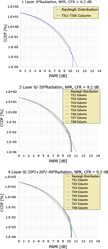
Fig. 7 shows PAPR for each TX column. Regarding 8 TXs in the horizontal direction, since 4 TXs (vertical 2 TXs × 2 polarization) in each vertical column radiates the same signal, PAPR of each 4 TXs column is also same.
By using NPR method, each output level vs. DL SINR at 1, 2 and 4 layer beams was respectively measured in the anechoic chamber. The results are summarized in Fig. 8.
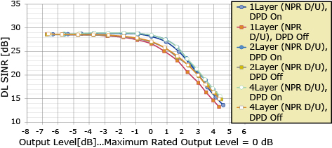
In the lower output level region in Fig. 8, since the low distortion level “I” is lower than the spectrum envelope of sinc function (SINC spectrum) from the existing OFDM subcarriers, alternative verification for DL DINR by NPR method is only effective in the higher output power region where distorted radiation is dominant. So DL SINR in the lower output power region is dominated by SINC spectrum and asymptotically approaches 29 dB.
It was confirmed in Fig. 8 that the multitone distorted radiation level and DL SINR appearing in each layer beam direction are almost similar regardless of the number of multiplexes.
Regarding the degree of nonlinearity exceeding the maximum rated output power level in the investigating condition where the peak level of AMP input signal is increased by CFR 9.2 dB from RMS level, DPD effect cannot be expected because the AMP output signal is hard clipped by the saturation level of AMP. Thus, DL SINR converges to the similar value for both DPD On/Off.
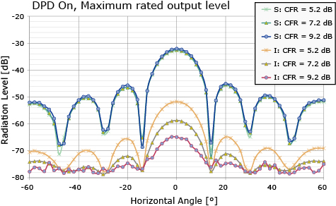
And in order to verify the peculiarity of the generated multitone distorted radiation pattern, after setting each TX output to the maximum output power + 5 dB (set to an output level where DL SINR is dominantly determined by nonlinear distortion) only for DPD On case, the angular spectrum of the desired wave “S” and multitone distorted radiation “I” when radiating 2 layer beams 0°/-20° and 4 layer beams 0°/±20°/-40° with the NPR condition are shown in Fig. 9.
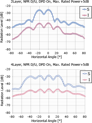
As a result, similar to the 1 layer beam radiation in Fig. 5, the multitone distorted radiation “I” is radiated to the same direction as each desired wave radiation “S”.
Since this verification was performed in the strong nonlinear region with the he maximum output power level + 5 dB, the S/I angular spectrum difference between DPD On/Off was small.
2.5 Impact of nonlinear distorted radiation and null on spatial multiplexing performance in the high output power region and improvement measures for AAS
In order to clarify the radiated power level and influence of nonlinear distorted radiation and null in spatial multiplexing, Fig. 10 shows the summary of 2 layer spatial multiplexing beam patterns to +10° (UT#1 direction from AAS) and -20° (UT#2 direction from AAS) directions in the anechoic chamber by using NPR method.
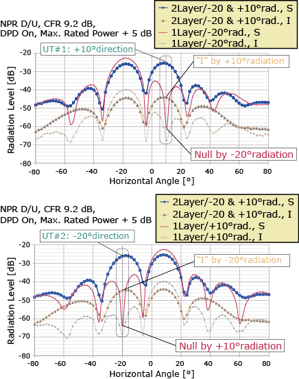
Regarding experimental conditions in Fig.10, the two UT radiations are set to the maximum total output power plus 5 dB with CFR setting of 9.2 dB and DPD On.
In Fig.10, along with the envelope angular spectrum for the desired wave radiation “S” in two UT direction and the envelope angular spectrum for the nonlinear distorted radiation “I” appearing with the desired wave radiation “S”, and also each angular spectrum for 2 layer beam to UT#1 and UT#2 are individually plotted.
One situation shows that null to +10°/UT#1 direction is generated accompanying the radiation pattern of the -20°/UT#2 (upper figure in Fig.10), and the other shows that null to -20°/UT#2 is generated accompanying the radiation of +10°/UT#1 (lower figure in Fig.10).
During spatial multiplexing in high output power region as shown in Fig.10, the nonlinear distortion component “I”, which greatly exceeds null level, is radiated to the same direction as each desired radiation “S”, so the DL SINR of each desired wave does not depend on null.
Thus, it can be confirmed that “I” degradation due to nonlinear distorted radiation is dominant to decide DL SINR degradation under the high output power region.
Consequently, in spatial multiplexing under such a strong nonlinear situation, improvement of nonlinear distortion by installing DPD is very effective as a necessary countermeasure for AAS.
However, when the nonlinear distortion has been already improved by DPD or when using in the lower DL output power region with high linearity, null generation with high accuracy shall be necessary in realizing superior spatial multiplexing performance with high DL SINR.
So in the above situation, it is important to use high precision DL CAL together to secure deep null depth.
Therefore, it is very effective to equip AAS with dual compensation of DPD and DL CAL, and it is possible to realize excellent spatial multiplexing performance with realizing the multilayer transmission to each UT with high DL SINR over the wide TX output power range3).
3. Conclusion
Since DL SINR is degraded predominantly by nonlinear distorted radiation generated to each UT direction, DPD shall be installed at each TX to suppress the nonlinear distortion generated especially by the TX PA.
In addition, the accuracy of deep null depth generated to avoid the interference to each UT direction with Zero-Forcing secured by removing the residual amplitude and phase variation between all transmitters and receivers by DL/UL CAL.
Thus, in terms of the TX, it was clarified that the double compensation scheme of DPD and high-precision DL CAL is very effective to achieve the excellent spatial multiplex (Massive MIMO) performance which is required to secure high spectral density over the wide TX output power range by Sub6 GHz band AAS for 5G.
4. Acknowledgement
This paper contains the results of “Research and Development for the Realization of 5th Generation Mobile Communication Systems”, which was commissioned by the Ministry of Internal Affairs and Communications.
References
- 1)Takuji Mochizuki et al.: Development of Low-SHF-Band Massive Element Active Antenna for 5G Mobile and Wireless Communications System, IEICE Society Conference, BCS-1-9, September 2016
- 2)Takuji Mochizuki et al.: Development of 4.65GHz Band Massive Element Active Antenna for 5G, IEICE General Conference, B-1-119, March 2018
- 3)Takuji Mochizuki et al.: Development of 4.65GHz Band Massive Element Active Antenna with Digital Predistortion (DPD) for 5G, IEICE Society Conference, BS-1-3, September 2018
- 4)Takuji Mochizuki et al.: A study of the Specificity of Nonlinear Distortion Radiation in Multitone Transmission using 4.65GHz Band Massive Element Active Antenna System for 5G, IEICE Technical Report on Technical Committee on Antennas and Propagation, A•P 2018 -178, February 2019
- 5)
- 6)Tadashi Takagi et al.: Intermodulation and Noise Power Ratio Analysis of Multiple-Carrier Amplifiers Using Discrete Fourier Transform, IEICE TRANSACTIONS on Electronics, vol. E77-C, no.6, pp.935-941, June 1994
- 7)Masatoshi Nakayama et al.: Distortion Calculation method of Micro Wave Amplifier: Mitsubishi Electric Technical Report, vol.71, no.10, pp.69-71, 1997
 Takana Kaho et al.: Carrier Power to Intermodulation-Distortion Power-Ratio-Increasing Technique in Active Phased-Array Antenna Systems, IEEE Transactions on Microwave Theory and Techniques, vol.50, no.12, pp.2987-2994, December 2002
Author’s Profile
MOCHIZUKI Takuji
Senior Professional
Wireless Access Development Department
Senior Professional
Wireless Access Development Department