Global Site
Displaying present location in the site.
Radio-over-Fiber Systems with 1-bit Outphasing Modulation for 5G/6G Indoor Wireless Communication
Vol.17 No.1 September 2023 Special Issue on Open Network Technologies — Network Technologies and Advanced Solutions at the Heart of an Open and Green Society PDF
PDFWe propose a radio-over-fiber (RoF) system with 1-bit outphasing modulation. The proposed RoF system does not require a power-hungry digital-to-analog converter in distributed antenna units and relaxes the operation speed of optical transceivers to reduce device cost. In the system, wide-band transmission with a signal bandwidth of 1 GHz was experimentally verified complying with the 3GPP standard for the adjacent channel leakage ratio (ACLR). Finally, the proposed RoF system has been shown to have a higher bandwidth efficiency compared with other systems. Therefore, the proposed RoF system provides a cost-effective in-building wireless solution for 5G and 6G mobile network systems.
1. Introduction
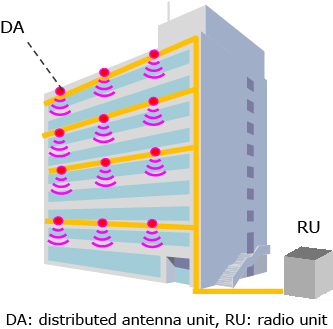
High-speed wireless communication using millimeter-wave technology has been used for 5G (fifth-generation mobile communication system) and is expected as a key technology in Beyond 5G/6G. When constructing an in-building wireless system with millimeter waves, it is necessary to consider its large propagation loss and high straightness. These make it difficult to propagate from base stations installed outdoors to indoor terminals. Since more than 80% of mobile communication traffic occurs in buildings1), it is essential to improve the quality of service (QoS) in such environments with many obstacles. While high-density deployment of millimeter-wave distributed antenna units (DAs) in these areas is effective in improving QoS, miniaturization, low power consumption, and cost reduction of DAs are necessary for practical use. A radio-over-fiber (RoF) system shown in Fig. 1 is a promising solution since it can provide the flexibility to install small and low-power DAs in indoor environments.
Current RoF systems are classified as digital RoF (DRoF), analog RoF (ARoF), and delta-sigma (ΔΣ) RoF, as shown in Fig. 2(a), (b), and (c), respectively. DRoF systems have been commercialized and widely used for indoor mobile network systems. Their DAs often require large power consumption and incur high cost because they are equipped with a high-performance digital-to-analog convertor (DAC) for wideband signal. ARoF DAs have the advantage of low power and small footprint because they do not require a DAC with large power consumption. ARoF systems require specific high-linear electrical-to-optical (E/O) and optical-electrical (O/E) convertors to avoid signal degradation due to distortion, leading to high cost. In contrast, ΔΣ RoF systems enable the implementation of low-cost RoF systems with small DAs since they do not require high-linear E/O and O/E devices or a power-hungry DAC in the DAs2)3). However, for wideband communication using millimeter waves, the sampling rate of the ΔΣ modulator needs to be increased, meaning a higher device speed is required for the optical transceiver, which drives up costs.
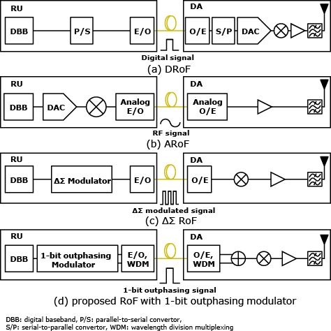
We propose a RoF system with 1-bit outphasing modulation, as shown in Fig. 2(d), to enable the use of low-cost optical devices.
2. Operation Principle of 1-bit Outphasing Modulation
Outphasing is a technique for transforming the original signal vector Sorg(t) with amplitude and phase modulations into a pair of outphasing signal vectors S1(t) and S2(t) with only phase modulation, as shown in Fig. 34). The amplitude A(t) and phase θ(t) are generated from the I/Q signal by polar coordinate conversion, as shown in the following equation,

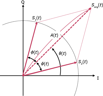
The S1(t) and S2(t) are generated in accordance with Eqs. (2a) and (2b), respectively,
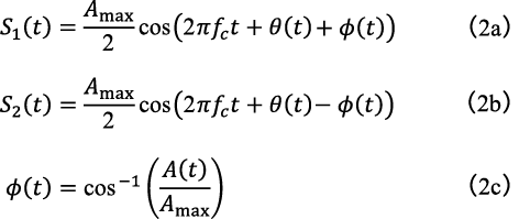
where, fc and Amax indicates carrier frequency and the maximum value in A(t), respectively. The principle of outphasing indicates that Sorg(t) is reconstructed by combining S1(t) and S2(t), as expressed with the following equation:

In the proposed RoF system, S1(t) and S2(t) are converted into rectangle wave signals S1b(t) and S2b(t) by comparing their amplitude with the value of zero. These are called 1-bit outphasing signals afterward.
Fig. 4 illustrates the waveforms of Sorg(t), a pair of S1b(t), S2b(t), and the conventional ΔΣ modulator output signal SΔΣ(t). The period of Sorg(t) is expressed as 1/fc, and those of S1b(t) and S2b(t) are also 1/fc. Thus, their pulse width is 1/(2fc), which means the required transition speed required of an optical transceiver is twice the fc. However, the transition speed of SΔΣ(t)equals the sampling rate fs, which is much higher than twice the fc, because this waveform is updated with the clock of fs. The lower transition speed enables the use of low-cost commercially available optical devices for millimeter-wave communications5)6). This is an advantage of the proposed RoF system over conventional ΔΣ RoF systems.

Moreover, the proposed system is less affected by timing jitter depending on pulse patterns. The proposed system basically has the uniform pulse pattern in which high and low levels are alternately switched around a time interval of 1/(2fc), while ΔΣ RoF systems have random pulse patterns, as shown in Fig. 4.
3. Circuit Configuration
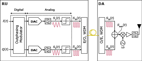
In section 3, we describe the circuit configuration for the RoF system with 1-bit outphasing modulation. Fig. 5 illustrates a block diagram of the proposed RoF system. In the radio unit (RU), the in-phase and quadrature (I/Q) of a digital baseband signal is given to the outphasing modulator and transformed to a pair of outphasing signals at an intermediate frequency fIF by digital signal processing. The output signals are input to the DACs and transformed into analog signals, S1(t) and S2(t), through anti-alias filters. These are then transformed into S1b(t) and S2b(t) at the comparators. These signals are transferred to a DA through an optical fiber cable. The wavelength division multiplexing (WDM) enables the RU to be connected to a DA through a single fiber. In the DA, S1b(t) and S2b(t) are combined to reconstruct the original signal at fIF. This combined signal is up-converted to a desired high-frequency band, e.g., a millimeter-wave band, then transmitted to the air after amplification and filtering.
4. Experimental Results
Fig. 6 shows the experimental setup to demonstrate the proposed RoF system. We used two types of 5G NR signals with 64QAM modulation at fBW of 100 MHz and 400 MHz, respectively. A pair of output signals from the outphasing modulator, S1(t) and S2(t), was generated in an arbitrary waveform generator (AWG). The generated signals were input to a quad small form-factor pluggable plus (QSFP+) module, which has maximum transmission rate of 10 Gbps per channels and 1,310 nm wavelength. The input signals were transformed into S1b(t) and S2b(t) during of E/O conversion. They were then transmitted to the receiver side through a 50 m single mode fiber (SMF) assuming the indoor environment. On the receiver side, the received signals were combined and measured using a spectrum analyzer. For reference, we also measured in case where the signals output from the AWG are directly input to the combiner without fiber transmission.
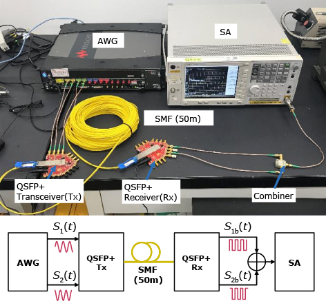
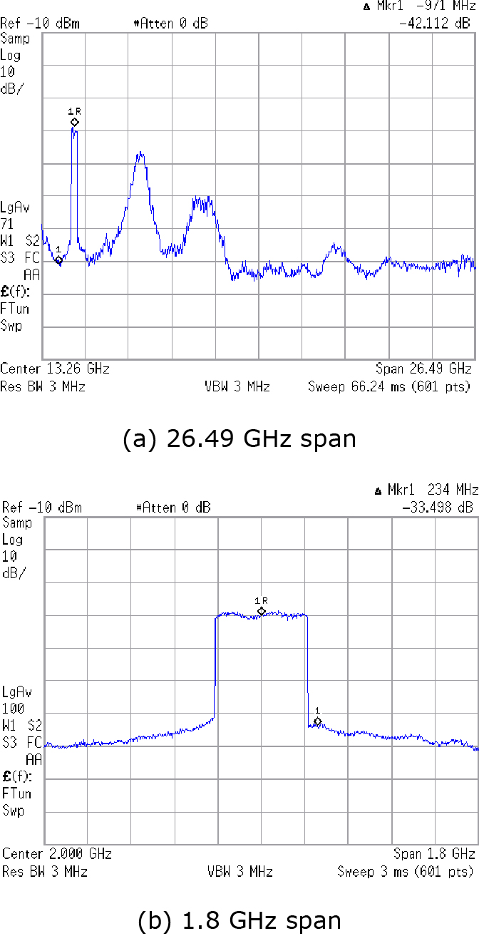
Fig. 7 shows the measured spectrum of Ssum(t) at fIF of 2 GHz and fBW of 400 MHz. The measured ACLR was −36 dB, in compliance with the 3GPP standard.
We measured the error vector magnitude (EVM) by a signal analyzer. Fig. 8 shows the results of the EVM measurement versus fIF. The solid lines indicate the EVM with the optical section, and the dotted lines indicate the EVM without the optical section as a reference. The circle plots indicate the EVM at fBW of 100 MHz and the diamond ones are that at fBW of 400 MHz. According to the 3GPP standard, the upper limit of EVM for 64QAM is defined as 8%7), and all cases in this measurement reached this limitation. The EVM was 3% or less for fIF of 1 and 2 GHz, 4.24% for 3GHz fIF and 4.68% for 4 GHz fIF in compliance with 64 QAM 3GPP standard. This means that an appropriate fIF should be chosen according to the system requirement of EVM.
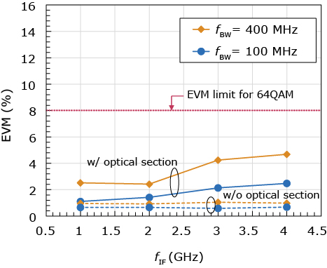
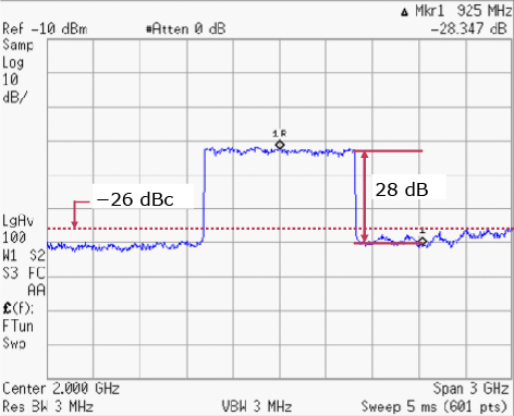
Fig. 9 shows the measured spectrum of Ssum(t) with 1 GHz bandwidth (10 x 100 MHz) OFDM signal at fIF of 2 GHz for Beyond 5G/6G. The measured SNR was more than 28 dB, and the difference between the mean powers of the desired and adjacent channels is 26 dBc or more. This means the ACLR complied with the 3GPP standard for 37 to 52.6 GHz band.
5. Discussion
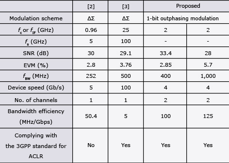
We discussed the performance of the proposed RoF system in terms of device cost, by comparing it with conventional RoF systems. Table shows the performance comparison of our proposed RoF system and conventional ΔΣ RoF systems. The device speed required for the optical transceiver is twice the fIF in our proposed RoF system while it is equal to the sampling rate in the ΔΣ RoF systems. The bandwidth efficiency is defined as the ratio of fBW to device speed required for each optical transceiver per channel2). Our proposed RoF system has the highest bandwidth efficiency, complying with the 3GPP standard for ACLR.
Table Proposed and conventional RoF systems.
6. CONCLUSION
We proposed a 1-bit outphasing modulation RoF system. Our system has the highest bandwidth efficiency complying with the 3GPP standard. This indicates that our system can be applied to 5G/6G indoor mobile networks at low cost.
7. Acknowledgments
This research is supported by the Ministry of Internal Affairs and Communications in Japan (JPJ000254).
References
- 1)
- 2)
- 3)
- 4)
- 5)
- 6)
- 7)3GPP TS 38.104: Base Station (BS) radio transmission and reception (Release 17), V17.4.0, December 2021
 J. Liu, J. Wu, J. Chen, P. Wang, and J. Zhang: Radio Resource Allocation in Buildings with Dense Femtocell Deployment, 2012 21st International Conference on Computer Communications and Networks (ICCCN), pp.1–5, August 2012
Copyright(C)2023 IEICE
Y. Kase, S. Hori, N. Oshima, K. Kunihiro: Radio-over-Fiber System with 1-bit Outphasing Modulation for 5G/6G Indoor Wireless Communication, IEICE Transactions on Electronics, July 2023. DOI: 10.1587/transele.2022ECP5043
Authors’ Profiles
HORI Shinichi
Professional
Wireless Access Development Department
Professional
Wireless Access Development Department
KASE Yuma
Wireless Access Development Department
Wireless Access Development Department
OSHIMA Naoki
Professional
Global Mobile Solution Department
Professional
Global Mobile Solution Department
KUNIHIRO Kazuaki
Senior Professional
Wireless Access Development Department
Senior Professional
Wireless Access Development Department