
Global Site
Displaying present location in the site.
Hayabusa2 — Autonomous Navigation, Guidance and Control System Supported Pinpoint Touchdowns on Asteroid Ryugu
Cutting-edge Technologies to Build a Better Future: Advanced Technologies in Space Applications PDF
PDFAfter arriving at the asteroid Ryugu, which orbits the Sun at a distance of over 300 million km from Earth, the Hayabusa2 asteroid explorer executed a pinpoint landing, touching down with a margin of error of about 1 m. This feat was largely made possible by Hayabusa2’s autonomous navigation, guidance and control system that surmounted the severe environmental conditions on the asteroid’s surface and the extended communication delay time. In this paper, we will introduce this critical system and outline the technology that makes it possible ― including the target markers (TMs) and the laser altimeter that facilitate pinpoint landings. We will also discuss the results of the mission, highlighting Hayabasa2’s principal achievements.
1. Introduction
Launched on December 3, 2014 via the H-IIA launch vehicle, the Hayabusa2 asteroid explorer rendezvoused with asteroid Ryugu in June 2018. The spacecraft successfully executed its first touchdown on February 22, 2019 to collect samples from the asteroid’s surface, followed by its second on July 11 to collect samples from the subsurface. With the return of the capsule to Earth on December 6, 2020, we have made a significant contribution to providing significant keys to the origin of the solar system and the origin of life on Earth.
Hayabusa2 landed twice on Ryugu, touching down each time with pinpoint precision with a margin of error of about 1 m. This impressive achievement was made possible by Hayabasa2’s autonomous navigation, guidance, and control system. What made this achievement particularly noteworthy were the restrictions imposed by the asteroid’s high-temperature environment and communication lag with operators back on Earth. This meant that the touchdown sequence could not be executed remotely while monitoring surface conditions; instead, the Hayabasa2 had to make the necessary judgments itself.
In this paper, we will look at the autonomous navigation, guidance, and control technology that made this extraordinary achievement possible. We will also discuss the system configuration of Hayabusa2 and the touchdown sequence, as well as highlighting some of the more notable mission results.
2. A Closer Look at Hayabusa2’s Pinpoint Touchdown
2.1 Hayabusa2’s autonomous navigation, guidance, and control system
Fig. 1 shows an external view of Hayabusa2’s autonomous navigation, guidance, and control system. As standard devices for navigation, guidance, and control, Hayabusa2 is equipped with a star tracker (STT) and an inertial reference unit (IRU) to estimate the attitude of the spacecraft, as well as a reaction control system (RCS) and a reaction wheel (RW) to control the position and attitude of the spacecraft. Landing support is provided by a light detection and ranging (LIDAR) laser altimeter to measure the distance to the asteroid, an optical navigation camera-W1 (ONC-W1) to grasp the spacecraft’s position relative to the asteroid, target markers (TMs) to provide landmarks on the asteroid, a flash (FLA) to make the TMs reflect light, and a laser range finder (LRF-S1) to measure four points on the asteroid’s surface to find the gradient and distance with respect to the local surface on the asteroid.
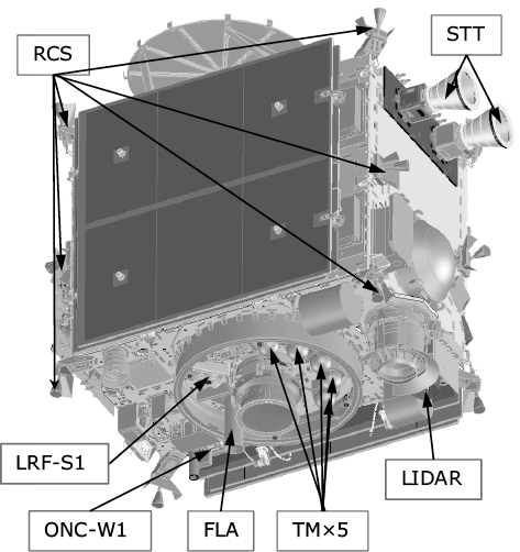
guidance, and control system.
2.2 Pinpoint touchdown sequence
An overview of the pinpoint touchdown sequence is shown in Table. Before touchdown, Hayabusa2 descended to an altitude of about 20 m and dropped the TM around the designated landing area, which was a flat surface determined earlier by image analysis of Ryugu. The spacecraft then returned to its home position at an altitude of 20 km above the asteroid.
Table Overview of the touchdown sequence.
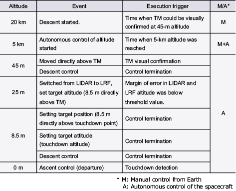
After calculating the relative position of the TM, the spacecraft began the touchdown maneuver, descending to an altitude of 45 m from where the ONC-W1 could visually confirm the dropped TM. The rotational velocity of Ryugu and the descending speed of the spacecraft were also taken into consideration.
The relative position of the Ryugu was estimated from images captured by the ONC-W1 from altitudes as low as 5 km. At this point, operators on Earth could still control the spacecraft. However, once the Hayabasa2 descended below the 5-km threshold, the communication delay resulting from errors in the estimation of the asteroid’s gravity made it impossible for Earth-based operators to accurately control the craft. Instead, the spacecraft executed autonomous altitude control using the LIDAR altitude information and safely descended to an altitude of 45 m.
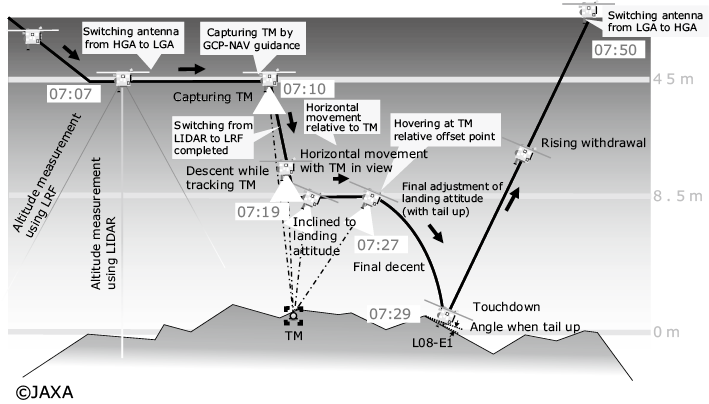
As soon as the TM was visually confirmed at the altitude of 45 m, the spacecraft switched to autonomous navigation, guidance and control while referencing the TM. Fig. 2 shows the touchdown sequence used when the altitude was below 45 m. By using the TM and the altitude information from the LIDAR and LRF to estimate the relative positions of the TM and by adjusting to achieve the position and attitude along the target trajectory, the spacecraft was able to accurately maneuver to the touchdown target point.
3. Component Technologies of the Autonomous Navigation, Guidance and Control System
Building on the lessons learned with the first Hayabusa, we improved the autonomous navigation, guidance and control system for Hayabusa2 to enable it to handle pinpoint touchdown on its own and collect samples from a crater artificially created by the small carry-on impactor (SCI) ― a procedure performed for the first time by Hayabusa2. A schematic diagram of the autonomous navigation, guidance and control system is shown in Fig. 3. Roughly speaking, this system includes technology for the estimation of the TM relative position and for the guidance sequence program.
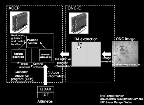
guidance and control system.
3.1 TM relative position estimation
The touchdown target point was specified in a coordinate system, specifically the navigation target (NT) coordinate system, with the target TM on the asteroid set as the origin of the coordinate system using close-up images obtained in the dry run for the landing. To estimate the position of the spacecraft in the NT coordinate system, information on the TM’s orientation and altitude when viewed from the spacecraft in the NT coordinate system was required.
Designed to recognize the TM, the ONC-E gave an imaging command and flashing command to the ONC-W1 and FLA respectively and extracted the TM by processing images. The TM was covered with retroreflective material, so it reflected the light from the FLA. After obtaining images with the FLA flashing and not flashing, the ONC-E generated difference images. The ONC-E applied binary processing, labeling processing, and center of gravity measurement to the difference images, calculating the TM’s CCD address in the ONC-W1’s angle of view.
Using the CCD address in the ONC-W1’s angle of view and the attitude estimation value during imaging, the attitude and orbit control processor (AOCP) calculated the TM’s orientation in the NT coordinate system when viewed from the spacecraft. The AOCP used the TM’s orientation and altitude information obtained from the LIDAR and LRF as updated observation information and estimated the position of the spacecraft in the NT coordinate system using a Kalman filter.
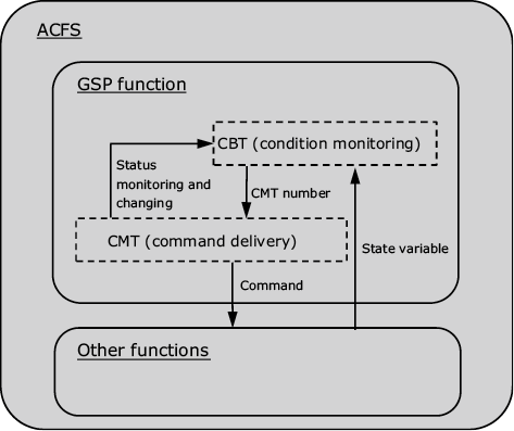
3.2 Guidance sequence program
Before Hayabasa2 arrived at Ryugu, the asteroid’s geographical features and environmental conditions were unclear, making it necessary that the craft be able to modify the touchdown sequence after arrival. To facilitate this, we added a programmable guidance sequence program (GSP) function to the attitude control flight software (ACFS), which is incorporated in the AOCP. The GSP function is composed of two tables: a conditional branch table (CBT) that monitors the status of the spacecraft and defines a branch accordingly and a command memory table (CMT) that executes a command according to the branch (Fig. 4). Thanks to the GSP function, commands could be transmitted while confirming the safety of the spacecraft during landing maneuvers up until the TM and descent control.
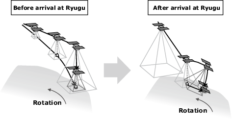
As a matter of fact, we had assumed that there would be flat areas with a radius of up to 50 m on the surface. Upon arrival, however, we discovered that the largest flat areas had a radius of only about 3 m. The original plan was to drop the TM, track it, and keep it in the ONC-W1’s field of view. Once the TM was positioned in an area with a 50-m radius that was suitable for landing, the spacecraft would descend to the surface and touch down as illustrated on the left in Fig. 5. This plan had to be scrapped in favor of the operation described in section 2.2, in which the craft would touch down at the target point specified by the relative position of the TM while using the dropped TM ― which were originally intended to support landing in the crater created by the SCI as illustrated on the right in Fig. 5 ― as landmarks.
There were other surprises as well. Dust blown up from the surface during the first landing caused the performance of the ONC-W1, LIDAR, and LRF to deteriorate, forcing us to adjust the TM visibility altitude and the LIDAR/LRF switching altitude. We modified the CBT and CMT for both functions, which ensured that we were able to execute the second landing without any problems.
4. Rendezvous and Operations
On February 22, 2019, Hayabusa2 departed its home position at 20 km above the asteroid and descended towards the surface, arriving on schedule at its pre-landing position, 45 m above the TM at 22:07 (UTC).
Fig. 6 shows the history of the CCD addresses of the TM measured in X and Y coordinates as viewed from the ONC-W1 and of the altitudes obtained from the LIDAR and the LRF. To begin with, a TM was captured at the edge of the ONC-W1’s angle of view at an altitude of 45 m. The spacecraft used autonomous control to move to a position directly above the TM, thereby moving the TM to the center of the angle of view. While maintaining its position directly above the TM, the spacecraft descended to an altitude of 8.5 m (Photo). At 8.5 m, the spacecraft moved to a position directly over the landing site as determined by the relative positions of the previously dropped TM. After changing the attitude to the touchdown attitude, we initiated descent control and detected touchdown at 22:29 (UTC)
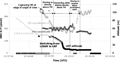
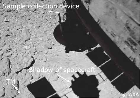
(approx. 8.5-m altitude).
5. Future Business Development
NEC’s autonomous navigation, guidance and control technology makes it possible for space vehicles to operate autonomously by capturing an object with image sensors, determining its relative position, and then approaching it. We have already seen how effective this technology is in supporting autonomous remote landings of space vehicles. It is also applicable to many other space activities including the assessment and removal of space debris, refueling in space, and so on. NEC’s participation in the Hayabusa and Hayabusa2 projects has enabled us to gain invaluable experience which we will be applying to new space exploration projects in the future.
6. Conclusion
NEC’s autonomous navigation, guidance and control technology ― first validated with Hayabusa ― played a critical role in supporting the successful landings of Hayabusa2. Now having proved its worth, this technology is being deployed in a wide range of space applications while an enhanced version will be deployed in the next long-range space mission.
After returning its samples to Earth, Hayabusa2 once again set off for another mission that will take 11 years in deep space. NEC is fully committed to supporting the success of this mission and those to come.
Authors’ Profiles
YASUDA Seiji
Assistant Manager
Space Systems Division
Assistant Manager
Space Systems Division
MATSUSHIMA Kota
Assistant Manager
Space Systems Division
Assistant Manager
Space Systems Division
KAMIYA Toshio
Manager
Space Systems Division
Manager
Space Systems Division
