
Global Site
Displaying present location in the site.
Development of Wireless Power Transfer Antenna Capable of Efficiently Transmitting High Power to Unmanned Underwater Vehicles
Cutting-edge Technologies to Build a Better Future: Advanced Technologies Permeate Every Facet of Our Lives PDF
PDFThis paper introduces the development of an underwater wireless power transfer (charging) antenna that is important for the operation of unmanned vehicles under the sea. Research and industrial activities are advancing in areas such as situational awareness, resource surveys, and the development of equipment for mining and extraction, and in recent years, unmanned underwater vehicles, like drones, are being widely used underwater. However, due to the limited range of wired power supply, and short operating time of battery-powered power supply, we have started to develop a wireless power transfer system for underwater use to improve operational efficiency. NEC has succeeded in developing a 50 W class underwater antenna using its original antenna technology obtained by R&D, but its capacity is small and its range of application is limited, so we began development of a practical level kilowatt class antenna.
1. Introduction
In recent oceanic development activities, the use of motorized unmanned vehicles has become increasingly widespread in the survey of seabed resources, and in the installation and maintenance of seabed equipment. The power for unmanned vehicles is supplied either by wired transfer from the sea surface or by a fuel cell or battery borne on the vehicle. Both these methods, however, are faced with drawbacks: wired power transfer limits the range of movement for the vehicle and battery-powered systems limit operating time. Fig. 1 shows an example of the operating cycle of a battery-driven unmanned underwater vehicle. In this cycle, the battery needs to be replaced manually, and considering the time it takes to surface, lift and return the vehicle to the work site, only 10% of the time required for the complete cycle is spent on the actual survey and inspection work. To combat these issues in operational efficiency, there is a growing need for underwater battery charging.
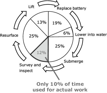
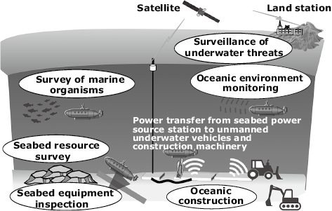
Fig. 2 shows an example of an unmanned vehicle operation under the sea. The purpose of this development is to improve the operational efficiency of various sensors, unmanned underwater vehicles, and unmanned construction machinery for surveying, inspecting, and monitoring the marine environment by supplying power underwater.
2. Issues with Underwater Power Transfer Technology
Wired power transfer can be easily achieved in the air using connectors and pins, but under the water, challenges can arise, such as the need to ensure rustproof and watertight structures, and the occurrence of short circuits due to debris entering the contact zone. There are also severe restrictions, for example, connection is difficult because unmanned vehicles can be swept away by the tide, which makes it necessary to use large-scale guiding systems. For this reason, simple noncontact power transfer technology with few restrictions is effective for underwater power transfers. However, even with noncontact power transfer, marine organisms will still adhere to the system, so it is important to maintain enough separation distance (clearance) between the transmitter and receiver so that power can be supplied even when organisms are attached.
There are various methods for noncontact power transfer, but the airborne wireless power transfer technology used in smart devices and EVs cannot be transferred directly for underwater use. This is because the energy loss in the medium is greater underwater than in the air, which drastically reduces the power transfer efficiency. As a result, a technology that enables highly efficient and high-power transfer in the sea is required.
3. Development of Underwater Power Transfer Technology
NEC has developed a power transfer technology that can achieve high power transfer efficiency even when the clearance between the transmitter and receiver antennas under the sea is large. The underwater antenna is a key element of this technology. The general method of wireless power transfer is to transmit power using an electromagnetic energy composed of electric and magnetic fields. In the far field where the electromagnetic waves propagate more than a few meters, the magnetic and electric field energies propagate while influencing each other. On the other hand, in the near field in which the propagation distance is only a few centimeters to a few tens of centimeters, either the magnetic field energy or the electric field energy becomes the main source of power transmitted from the transmitter to the receiver. The magnetic field energy is not dependent on the medium (air, fresh water or seawater) so there is no change in propagation characteristic. Meanwhile, the electric field energy is greatly dependent on the medium and a special phenomenon is observed under the sea. It is known that in seawater, where salt (NaCl) is the main component, applying an electric field causes the Na+ and Cl- ions to migrate, resulting in the flow of electric current. In other words, the electric field energy emitted from the transmitter antenna in the sea is consumed as kinetic energy when the electric charge (ions) moves, so the propagation loss of the electric field energy becomes larger than in the air, and the energy reaching the receiver antenna becomes minimal.
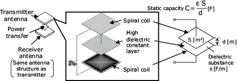
To solve this issue, a technique for trapping the electric field energy temporarily in the transmission circuit network of the antenna and then radiating the electric field energy was devised1)2). Specifically, a dielectric layer with a relatively high dielectric constant is inserted between the spiral coils on the top and bottom (Fig. 3) in order to let the antenna act as a large parallel-plate capacitor. This structure, called the “dielectric assist structure”, makes it possible to emit a high electric field energy and propagate it over a far distance. The transmitter and receiver antennas are given the same structure in order to transmit power at the maximum energy by making use of the phenomenon of resonance.
4. Performance Test of 50 W Class Antenna
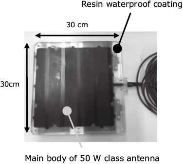
It is necessary to demonstrate the effectiveness of the antenna with the developed dielectric assist structure. However, since a license is required under the Japanese Radio Law for wireless power transfer systems with an input power over 50 W, we manufactured a 50 W class antenna that operates at less than 50 W to confirm basic performance. The external view of the 50 W class antenna (30 cm W x 30 cm H x 3 cm Thickness) is shown in Fig. 4. The high dielectric constant layer is sandwiched between the upper and lower spiral coils and coated with resin.
The propagation characteristics of the magnetic and electric fields of the 50 W class antenna were measured in the sea. The results of the magnetic field propagation characteristics confirmed that they are independent of the medium and remained the same in different mediums such as air, fresh water, and seawater. On the other hand, as shown in Fig. 5, the propagation characteristics of the electric field showed a slope of 0.29 dB/cm in the sea compared to a slope of 0.66 dB/cm in the air, which halved the propagation loss with respect to the clearance between the transmitter and receiver antennas, confirming the effectiveness of the dielectric assist structure.
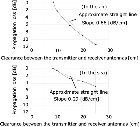
(Top: In the air. Bottom: In the sea).
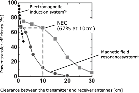
Fig. 6 shows the measurement results for the clearance between the transmitter and receiver antennas and for the power transfer efficiency. The results confirm that the dielectric assist structure is capable of transferring 67% of power when the clearance between the transmitter and receiver antennas is 10 cm5). This 67% efficiency is equivalent to a clearance of about 1cm in the electromagnetic induction method used in smartphones, and about 2cm in the magnetic field resonance method used in electric vehicles. Again, the antenna developed by NEC using a dielectric assist structure can maintain high power transmission efficiency even when the clearance between the transmitter and receiver antennas is large in the sea, and is therefore expected to be applied to unmanned underwater vehicles.
Although the basic performance was confirmed using the 50 W class antenna, 50 W is too low; it is just enough power to light a single bulb, and its applications are therefore limited. Development of a kilowatt class antenna is required to meet various needs.
The 50 W class antenna has been recognized as having the best performance in terms of clearance between the transmitter and receiver antennas by the FCT* of the U.S. Department of Defense, and the U.S. Navy has expressed strong expectations for higher power antennas.
- *FCT stands for Foreign Comparative Testing. It is a program for assessing products and technology with a high level of technology from allied nations in order to achieve defense requirements quickly and economically.
5. Development of Kilowatt Class Antenna
In order to accurately determine the basic performance of the 50 W class antenna, the spiral coil formation in the antenna was based on a laminated printed circuit board manufacturing method to set coils opposite to each other. With the development of the kilowatt-class antenna, however, coil formation with thicker rectangular copper wires of 1 mm or more are required to carry large currents. This necessitated a review of the manufacturing process itself and the process for attaching the upper and lower coils was modified. As a result, gaps due to air bubbles or delamination are easily formed between the high dielectric constant layer and the coils above and below it, and the problem of partial discharge due to concentration of electric fields in the gaps emerged once again. Therefore, we have been studying countermeasures against the partial discharge problem through preliminary experiments using several dielectric layers. As a result, the use of interlayer adhesive sheets with glass cloth as a high dielectric layer between coils is expected to enhance the insulation strength.
We are currently in the process of creating a prototype of a kilowatt class antenna based on the fabrication process above, and we have obtained evaluation results of the power transfer efficiency with an applied input power from 50 W to 500 W as shown in Fig. 7. The measurement conditions are airborne and the antennas are in close contact with each other, and it was confirmed that the power transfer efficiency was 61.9% at 50 W input voltage, which started to drop gradually at around 300 W input power to 49.3% at 500 W input power. This drop in the power transfer is presumed to be caused by impedance mismatch due to the skin effect based on the input power. We are planning to add a variable matching device aimed at maintaining a 60% or higher power transfer efficiency even when high power is applied.
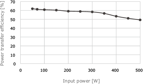
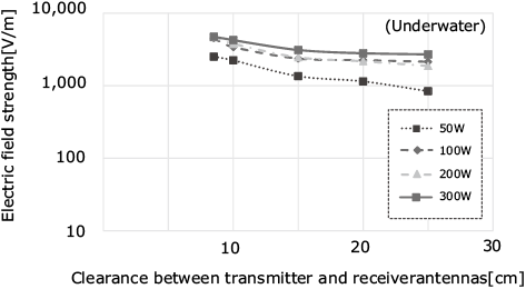
Fig. 8 shows the propagation characteristics of the electric field strength with respect to the clearance between the transmitter and receiver antennas. Here, the input power is varied from 50 W to 300 W, where the decrease in power transfer efficiency described in Fig. 7 begins to occur. Figure 8 shows that the electric field strength increases following the increase in input power and also that the variation difference (loss) of the electric field strength with respect to the clearance decreases accordingly. This is also an effect of the dielectric assist structure and shows that highly efficient high-power transfer is possible with a wide range of clearance.
6. Conclusion
NEC developed a dielectric assist structure for use as an underwater antenna capable of power transfer to unmanned underwater vehicles and unmanned construction machinery, and demonstrated the basic performance with a 50 W class antenna. Furthermore, in consideration of the practical use, NEC also started developing a kilowatt class antenna to meet a wider range of needs. Although we still have a way to go to meet this higher power requirement, modification of the fabrication process, review of materials and preliminary experiments have made it possible to confirm the power transfer efficiency up to an input power of 500 W. For the future, we plan to improve the power transfer efficiency (target 60% or more) under higher power by using a variable matching device to deal with variation in impedance of the power transfer path. In addition, we plan to assess the application of kilowatt class power while checking the resistance to partial discharges. We expect that implementation of the kilowatt class antenna will increase the applications to underwater wireless power transfer, and that this will also expand the world of IoT in the underwater world in the near future.
Part of the research herein was subsidized by the Underwater Wireless Power Transfer Project (ID: 2018495335) of the Nippon Foundation.

Reference
- 1)Makoto Ogawa et al.: Development of an Antenna Specialized to the seawater, MAST Asia 2019, 2019
- 2)Makoto Ogawa et al.: Development of an Antenna for Underwater Wireless Power Charging and Communication, Proceedings of the 2018 IEICE Society Conference, 2018
- 3)Jun Han et al.: Noncontact power supply for seafloor geodetic observing robot system, Journal of Marine Science and Technology, 12(3), pp.182-189, 2007
- 4)Gino Virgilio Tibajia et al.: Development and evaluation of simultaneous wireless transmission of power and data for oceanographic devices, IEEE SENSORS, 2011
- 5)S. Yoshida et al.: Underwater Wireless Power Transfer for non-fixed Unmanned Underwater Vehicle in the Ocean, 2016 IEEE/OES Autonomous Underwater Vehicles (AUV), 2016
Authors’ Profiles
OGAWA Makoto
Assistant Manager
Radio Application, Guidance and Electro-Optics Division
Assistant Manager
Radio Application, Guidance and Electro-Optics Division
YAMAMOTO Mitsuru
Senior Expert
Radio Application, Guidance and Electro-Optics Division
Senior Expert
Radio Application, Guidance and Electro-Optics Division