Global Site
Breadcrumb navigation
LIR can capture even night clouds
Ryouichi Kashikawa, LIR Engineer, NEC TOSHIBA Space Systems
AKATSUKI has five "eyes," i.e. five cameras, for capturing images of Venus. Each camera captures different wavelengths. AKATSUKI's cameras include the IR1 (for capturing wavelengths of about 1 μm), the IR2 (for wavelengths of about 2 μm), and the LIR (long-wave infrared), which uses the 10 μm wavelength. These three cameras for capturing the infrared region are complemented by the UVI, or ultraviolet imager, which captures the ultraviolet wavelengths, and the LAC, or lightning and airglow camera, which captures lightning and airglows at visible wavelengths. NEC was responsible for developing the LIR and UVI, as well as the mission system computer called DE for global control of the cameras and image processing. Ryouichi Kashikawa, the space camera expert who developed the LIR, shared with us the story of the development of this camera.
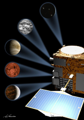
From the top: Lighting: Lighting and airglow camera (LAC),
temperature distribution of clouds: Long-wave infrared camera (LIR),
chemical substances at cloud tops: ultraviolet imager (UVI),
ground surface: 1 μm camera (IR1), lower atmosphere: 2 μm camera (IR2)
- What kind of camera is the LIR camera you were in charge of?
Kashikawa: The LIR is a camera that captures the thermal infrared rays in the 8 to 12 μm band that are radiated according to the temperature of the observation target. The photographic subject is the cloud top layer and the observation temperature range is 220 K to 250 K (-53°C to -23°C). Many may envision an extremely hot place with temperatures of a few hundred degrees when thinking of Venus, but this describes the surface of Venus only. On Venus, like on Earth, the higher you go, the colder it gets. Because the LIR observes the cloud tops, the principal investigators set this low LIR observation temperature range.
- What kind of sensor is the bolometer, which was employed for the first time in a space camera in the LIR?
Kashikawa: Most image sensors are CCDs, which are used in digital cameras and video cameras. Such sensors put out signals by converting the electrons excited in the semiconductor by the incident light into a voltage. However, creating an infrared sensor with the same technique (photon detection) would result in greater excitation from the temperature of the sensor itself than the signal unless the sensor is refrigerated.
On the other hand, the bolometer is a resistor that converts the received infrared rays into heat. When the temperature changes, so does the electrical resistance, and voltage fluctuations are read by passing a current through the bolometer. This technique (called thermal detection) has the significant advantage of not requiring refrigeration, allowing the creation of low-weight cameras that use less power, reducing the risk of equipment failure.
Regarding the statement that the LIR was the first case of an uncooled bolometer sensor being used in a space camera, I don't think we checked with all manufacturers, including overseas ones. At any rate, there appear to be no other cases, even overseas, of Venusian observation with the LIR's wavelength range.
- Talking about infrared cameras, did the cameras that were installed at the immigration security gates in airports at the time of the H1N1 flu outbreak in order to measure people's body temperature, showing the faces of those with a fever in red, use that bolometer?
Kashikawa: Yes, I believe so. NEC's Guidance and Electro-Optics Division originally developed bolometer infrared cameras for ground use, and one of the principal investigators who learned that such cameras were being sold for civilian applications since 2004 suggested the use of this technology for the observation of Venus. This launched the development of the LIR camera.
NEC's infrared technology
NEC's infrared technology operations, which take place within the company in Japan, cover the whole range from research on uncooled infrared sensors to production. Using our advanced semiconductor technologies, we have achieved the world's finest pixel pitch as well as superb temperature resolution and sensitivity. NEC's proprietary infrared technology is also used in circuits used in infrared modules for sensor driving, readout, image signal processing, and so on, realizing high image uniformity and stability.
Memories of the installation of cameras for measuring body temperature at immigration security gates in airports, at NEC headquarters, and other locations during the spread of the H1N1 flu are still fresh, but this technology can be used for various other applications, including disaster prevention and aircraft flight.
- And so you were put in charge of the LIR camera.
Kashikawa: Actually, I don't really think I fit the "space camera expert" description given at the beginning of this article, but I was given the chance of participating in various projects. I was put in charge of star sensors for the radio astronomy satellite HALCA (launched in 1997) and the Advanced Land Observing Satellite Daichi (launched in January 2006), and I was in charge of satellite acquisition cameras for the Optical Inter-orbit Communications Engineering Test Satellite Kirari. And that's how I came to be in charge of the LIR's development.
- Reworking cameras that were originally designed for civilian use for space application must have presented various challenges.
Kashikawa: All the cameras I had been in charge of before were CCD cameras, and thus the bolometer was a first for all on the team, me included. I started by having a desk set up in the NEC camera development division that developed bolometer cameras for civilian use and learning the basic usage methods, including copious study of related technical materials, for about one month.
Cameras for civilian use can use the latest advanced ICs, which integrate an array of extremely useful functions on a single chip, but unfortunately we are limited to parts that have been approved for use in outer space. For example, wet process and resin parts cannot be used as is, and most high-density processes employed in civilian ICs are weak against radiation. Thus, we have to combine general-purpose amplifiers, diodes, transistors and other parts that are guaranteed safe for space use, in order to realize circuits with equivalent functions, and as a result, a circuit that can be realized with just a few ICs for civilian cameras takes up a whole printed circuit board.
- That's interesting. "Compact" and "lightweight" usually come to mind with regard to space applications.
Kashikawa: Yes; and one more thing: Actually, just mounting the various circuits of an IC on a printed circuit board will not get you a working device. Extending circuit wiring for the same signal frequency band, which may for example cause a difference in potential where this is not permissible, ends up degrading performance. Thus, on top of making the circuit configuration as simple as possible, determining which wiring parts on the printed circuit board to shorten, and which to make thicker, is key to optimizing performance.
This is what designing space equipment is about: Just squeaking by while aiming for the lightest weight and highest performance possible under such constraints.
But even though we may mutter to ourselves that the civilian divisions have it good, being able to use all these great parts, making circuits by combining transistors, diodes and so on is actually the most fun part.
Another major difference with civilian cameras is the brightness of the photographic subject. The intensity of the light emitted from a body is proportional to the fourth power of the temperature of that body. The temperature condition of the photographic subject of a civilian camera is presumed to be around 300 K (27°C), while that of the top layer of clouds on Venus is 200 K (-53°C). This ratio is compounded by the fourth power proportionality, so that the intensity of the light that reaches the camera is less than one fifth.
- That's the Stefan-Boltzmann law*1, isn't it?
- *1: Stefan-Boltzmann law: A law stating that the radiance and radiant exitance of a black body (perfect emitter and perfect absorber of radiation) is proportional to the fourth power of the absolute temperature of that body.
Kashikawa: Yes. Moreover, because the peak of the spectral range falls outside the sensitivity range of 8 μm to 12 μm, the signal components are even smaller. Therefore, the sensor's sensitivity must be pushed as high as possible, causing the variations in the bolometer's element resistance between adjacent pixels to exceed the circuit's range.
- Causing the same problem as in the case of the photon detection sensor mentioned earlier, correct?
Kashikawa: That's right. But actually the nature of the variation differs. In the photon detection type, the number of electrons excited by the sensor's own temperature, etc., always has a degree of variation to the order of the square root of that number, whereas the element resistance of the bolometer does not vary over time and thus can be corrected.
Actually, the bolometer sensor is provided with a function to change the bias current passed through each element on a pixel-by-pixel basis. Whether the variation is on the + side or the - side of the circuit range is read for each pixel by a subsequent stage circuit, and these values are then returned to the bolometer sensor as the bias current correction parameter.
- Would accurate calibration of this correction yield clear images of the clouds on Venus?
Kashikawa: Actually, there is more to it. Just correcting the bias current inside the bolometer sensor allows us just to contain the variation within the range of the subsequent circuits. The LIR converts the output of each pixel into a 12-bit digital value; in other words the data is expressed using 4096 values each representing a different level. But among these 4096 levels, the variation in the observation target data is to the order of just a few levels per 1°C, whereas without further processing, the bolometer pixel variation would exceed 1,000 levels even at that point, precluding the acquisition of usable images.
This is remedied by installing a motor-driven shutter in front of the camera lens and simply shooting the rear of the shutter. The obtained image data expresses in raw form the variations of the various pixels of the bolometer. Next, the surface of Venus is shot with the shutter open, and an accurate image is obtained by subtracting the pixel variations of the first image from the second image.
- Good observation data cannot be obtained unless all this is done, right?
Kashikawa: Right. The processing to cancel the differences between these two images is done with a piece of equipment called the DE (Digital Electronics image processor; for details, click here). The LIR performs bias current correction for each pixel as described above in real time, and the image data, which still contains more than 1000 levels of variations, must be passed to the DE without distorting the image signal that has just a few levels of variation by burying it in noise.
In order to realize these functions and performance, the LIR was designed using a larger number of development steps than usual. Normally, a working prototype model for ground testing is fabricated and then the flight model for actual launch is created, but in the case of the LIR, an in-house research budget was established prior to the fabrication of the prototype model, and a test model for evaluating the performance of the analog circuits and verifying the basic operation of other major circuits was created. In the case of most circuits, the PCB pattern is automatically generated from the circuit diagram, but this time, in the case of a six-layer PCB for example, circuit diagrams were traced by hand on six separate sheets of double-sized paper, for the purpose of deciding which sections of the wiring to make shorter, and which ones to make thicker, as mentioned above, taking into account interference among the six overlapping layers. Interestingly, when you get absorbed in pattern design, the flows of people on the train platform in the morning and evening start looking like electron flows.
In the end, we somehow managed to achieve our targeted level of performance.
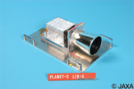
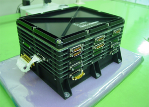
The completed LIR flight model weighed 2.1 kg for the main unit only, and the power block was placed in a different enclosure. The use of a separate enclosure means additional weight, a luxury in space design, but this separation was necessary in order to minimize the effect of the heat emitted by the power supply on observation, and thus we asked the systems people to attach the main unit by itself to a mounting panel with a certain degree of temperature stability. The temperature of the bolometer element proper was controlled to a stability of within 0.1°C by a circuit that took up a whole printed circuit board—this circuit could be realized with just a few ICs for civilian cameras as I mentioned before.
- How do you feel about having developed the first bolometer used on a satellite?
Kashikawa: "I didn't do it on my own" pretty much sums it up. I received a tremendous amount of support from the principal investigators, several NEC divisions, and all those at the Guidance and Electro-Optics Division, which developed the civilian bolometer cameras. Many different manufacturers also participated in the LIR project. Showa Optronics, an NEC Group company, provided high-resolution, low-distortion lenses, and Tamagawa Seiki provided ultra-compact shutter motors. Another company, Axis Corporation, also supported development activities from the initial prototyping stage with its strong technological capabilities. True gratitude to all these parties is how I really feel.
I think that the LIR's development will be marked by three major moments of joy. The first one was when the prototype put out a clear image. The next one was when, after its launch, AKATSUKI photographed the Earth as a camera function test. Although the picture was taken from the nightside of the Earth, the LIR was able to show a round Earth by capturing the infrared light it radiates. The principal investigators too were overcome with joy when we received the image of the round Earth.
I expect the third time to be when AKATSUKI enters Venus's orbit and captures beautiful images of the planet.
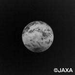
Photo of the Earth taken by the LIR of AKATSUKI
during the early-stage function test
As the LIR flies toward Venus, Kashikawa already envisions its future travels to the far reaches of the solar system.
Researched and written by Shinya Matsuura, October 27, 2010
Image processor DE (Digital Electronics)
The image data recorded by AKATSUKI is transmitted back to Earth via radio waves, in compressed form due to transmission capacity limitations.
There are various compression methods, including JPEG 2000, an international standard widely used in digital cameras and personal computers. While JPEG 2000 delivers high image quality, its processing is quite slow, making it unsuitable for compressing and transmitting voluminous data such as the large number of images to be taken by AKATSUKI over the course of a two-hour observation period.
Initially, the development of a JPEG2000 encoder ASIC was considered due to the fast compression speed required for the DE operation. In the end, this idea was not realized, because StarPixel, a new image compression method developed by NEC, achieved a sufficient processing speed even though it is implemented by software, and the total power consumption was lower than if the encoder ASIC was incorporated.
StarPixel enables a compact processing algorithm that delivers a sufficient compression speed. The compression ratio is almost the same as that of JPEG 2000. The fast processing speed allows software-based implementation without the need to develop a dedicated LSI as for JPEG 2000.
At present, the observation data transmitted back to Earth by AKATSUKI consists almost entirely of data compressed with StarPixel. JPEG 2000 software is also provided as a backup but it has barely been used until now.
StarPixel is also used by InfoFrame ImagingCore, a group of image processing components used for converting the still pictures managed by the InfoFrame data management software.
Ryouichi Kashikawa,
Assistant Manager, Technical Headquarters,
NEC TOSHIBA Space Systems
Kashikawa joined NEC in 1987. Since then, he has participated in the development of electronic devices in space divisions, including telemetry equipment for the M-3SII and H-2 rockets, various microgravity experiment equipment, and has been in charge of cameras and other devices for projects such as MUSES (HALCA), ALOS (Daichi), and OICETS (Kirari). He has been in charge of the LIR for PLANET-C (AKATSUKI) since 2004.