Global Site
Breadcrumb navigation
Connecting Venus and Earth with a Flat Antenna
Antenna engineer: Osamu Amano, NEC TOSHIBA Space Systems
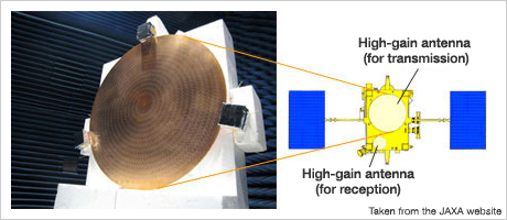
If we compare Hayabusa and AKATSUKI, there is one major difference that is immediately obvious. Hayabusa has a large parabolic antenna*1, but AKATSUKI does not. Where one would expect to find this antenna, there are instead two white discs, one large and one small.
Each disc is in fact a new type of flat antenna. This type of antenna is more advanced, lighter, and easier to build than Hayabusa's parabolic antenna. Because AKATSUKI is bound for Venus, which is closer to the Sun than Earth, the probe will be exposed to strong sunlight. The new flat antenna was developed to ensure reliable communication, given the environmental conditions of Venus. The man who was in charge of development, Osamu Amano, has been involved in developing satellite antennas for almost 30 years.
- *1 Parabolic antenna: This is an antenna that has a reflector with a bowl-shaped parabolic surface. A radio wave transceiver is positioned at the focus of this surface. Radio waves that strike the surface converge at the focus, and, conversely, radio waves emitted from the focus are reflected by the parabolic surface and emitted in one direction as a concentrated beam.
- Have you been involved in antenna research and development ever since you started working at NEC?
Amano: That's right. I was involved in antenna research even in college, and I started working at NEC in 1981 because I figured this company would give me the chance I wanted. I've been busy with antennas ever since. The first satellite I was involved in was the magnetosphere observation satellite OHZORA (which was launched in 1984). I was in charge of many Institute of Space and Astronautical Science (ISAS) satellites after that.
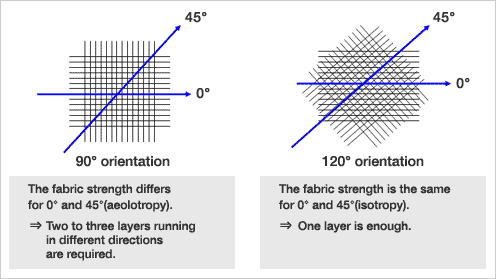
Of those projects, the high-gain antenna*2 of the Mars explorer NOZOMI (1998) marked a turning point for me. The NOZOMI antenna had to be both extremely light and capable of super long distance communication between Earth and Mars. At first, I tried using carbon-fiber fabric for the parabolic reflective surface, but, in the case of normal weaving, for which two sets of fibers are interlaced at a right angle to each other, the strength of the fabric depended on the direction in which force was applied, so two to three layers of fabric had to be overlapped to achieve the required strength. Therefore, I used a triaxial weaving method in which carbon fibers run in three directions that are 120 degrees apart to achieve the required strength with one layer of fabric and reduce the weight of the antenna from 16 kg to 7 kg. This technique was used later for the Hayabusa asteroid probe and KAGUYA lunar probe.
- *2 High-gain antenna: This type of antenna utilizes a unique structure that offers increased sensitivity. A parabolic antenna is one type of high-gain antenna. High-gain antennas are capable of high-speed communication, which makes it possible to transmit and receive large amounts of data. However, because such antennas become incapable of communication if the direction they are facing is even a little off, they must be correctly aimed with a high degree of precision. In addition to high-gain antennas, medium-gain and low-gain antennas are available. These antennas are not very sensitive, but, unlike high-gain antennas, they are capable of communication in various directions and are therefore used for certain purposes.
- Why did you develop a flat antenna for use with AKATSUKI instead of using a parabolic antenna?
Amano: The first problem for AKATSUKI is that a parabolic surface condenses sunlight. A parabolic antenna has a power line at its focus that is used to send radio waves, but, because the sunlight near Venus is approximately twice as strong as that near Earth, condensing the sunlight at the power line would cause it to overheat. It was also necessary to make AKATSUKI lighter and increase the freedom with which the peripheral engine can be positioned, and using a flat antenna solved these problems.
- Was the flat antenna proposed to the ISAS by NEC?
Amano: That's right. However, at the time of the proposal, I still didn't know how or when the antenna would be built. Therefore, I worked with the scientists at Professor Makoto Ando's research lab at the Tokyo Institute of Technology, which has been involved in flat antenna research for over 10 years, to develop the new antenna for AKATSUKI.
- About how long did development take?
Amano: I submitted a report that detailed the trade-offs of using a flat antenna versus a parabolic antenna in March 2005. By December 2006, I confirmed that my test antenna was capable of the required performance, so I guess the actual development took about a year and a half. That's pretty fast as far as product development goes.
- What exactly is the flat antenna, and how does it work? Based on the photos, the antenna just looks like a metallic surface with a bunch of L-shaped grooves cut into it.
Amano: The antenna is called a radial line slot antenna (RLSA). When you look at the radio wave emitting surface, you can see L-shaped grooves (which we call slots) cut in a spiral pattern. All of these slots emit radio waves that have the same amplitude and phase. The slot size and arrangement that result in these characteristics are determined using a computer, and the analysis techniques and software that are used represent design know-how.
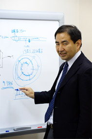
To understand how the antenna works, it's probably best to look at a figure. (With that, Mr. Amano started drawing a figure on the whiteboard.)
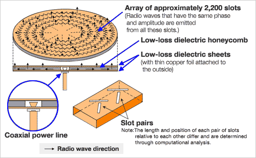
As might be expected, a honeycomb core*3 is sandwiched in the thin gap between the two dielectric sheets. Because there must not be any loss, the sheets and core are made of low-loss material. There is a power line that emits radio waves at the center, and these waves are emitted to the outside of the disc.
- *3 Honeycomb core: A beehive is one type of honeycomb, and a honeycomb core is a material that has a structure consisting of regular hexagonal shapes or columns that are lined up without gaps between them. Because honeycomb cores are light and sturdy, they are widely used for applications such as airplanes, rockets, and satellites.
As radio waves propagate, they are emitted from the slots in the metal foil on the top. The antenna is referred to as radial line powered because radio waves are radially emitted from the center to the outside, and the antenna is referred to as a slot array because there are many slots cut into it.
The antenna has an efficiency of 58%, which means that, of the energy emitted from the power line, 58% is transmitted from the antenna as radio waves.
High-gain antenna equipped by AKATSUKI
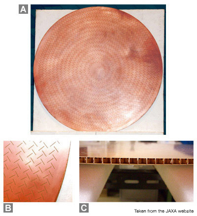
- A: Engineering model
- B: This photo shows an enlargement of part of the antenna (in which slots are visible).
The antenna has approximately 2,200 slots (antenna elements).
One T-shaped pair is formed by every two elements, and these pairs create circularly polarized waves. - C: Honeycomb core structure
- How much more efficient is that than a parabolic antenna?
Amano: A parabolic antenna has an efficiency of approximately 50 to 60%. However, for a parabolic antenna, the power line on the antenna has to be wired. After factoring in the energy loss due to the wiring, the flat antenna offers higher efficiency. Hayabusa's high-gain antenna had a diameter of 1.6 m, but AKATSUKI's flat antenna achieves the same performance despite having a diameter of only 90 cm. In addition, because the power line on the parabolic surface of a parabolic antenna has to be attached at the correct position, assembling such an antenna is complicated. In contrast, assembling a flat antenna is simple because all you have to do is attach flat parts.
- The flat antenna is also lighter, right?
Amano: Yeah, a flat antenna only weighs 1 kg. However, unlike a parabolic antenna, a single flat antenna cannot be used for multiple different frequencies. Therefore, two flat antennas were required, one for transmission and one for reception, for a total of 2 kg. A cover was also attached to prevent sunlight from striking the antennas, causing the satellite to overheat. The cover is called a radome*4 and weighs 2 kg. That makes the total weight 4 kg. This means that the AKATSUKI antennas weigh less than the Hayabusa antenna, which weighed 7 kg.
- *4 Radome: This cover is used to protect a radar antenna. Radome is a portmanteau of the words radar and dome.

- I see you call it a radome for satellites as well. That word is often used for airplanes. The name radome makes sense for a dome that covers radar. It sure doesn't look like a dome though (laughs).
Amano: That's right, the antennas are flat so the radome is actually flat, not a dome. This posed a challenge, so I initially considered painting the antenna with sunlight reflecting white paint instead of using a radome that would increase the satellite weight. However, the typically used organic paint would deteriorate and turn black near Venus's orbit, due to the strong sunlight there.
- Once the paint turns black, heat can get in, right?
Amano: That's right. Therefore, I tried using paint that is resistant to deterioration, but, even though I painted 2,200 slots, I could not achieve the necessary performance when testing the antenna, so I ended up attaching a radome after all. There are many such cases of trial and error during development.
- Flat antennas offer many advantages, so there are a wide range of applications for them other than satellites as well, right?
Amano: Yes, and I am also considering various possibilities for ground use. In terms of antenna development, I want to widen the usable frequency bandwidth and handle multi-beams that have several power lines.
AKATSUKI's flat antenna represents the most recent accomplishment in the life of Osamu Amano, an engineer who has 30 years of satellite experience. The technology pioneered by this engineer will soon lead to images of Venus being transmitted to Earth, thereby connecting the two planets.
When asked, Mr. Amano responded that he wants a successor. He added that he wants to train a young engineer to whom he can pass on his skills and who is capable of developing new antennas.
Researched and written by Shinya Matsuura, October 13, 2010
Osamu Amano,
antenna engineer, NEC TOSHIBA Space Systems
Joined the company in 1981. He has been engaged in antenna analysis program development since his college days.
Since he started working at NEC, he has been in charge of a wide range of antenna hardware, ranging from low-gain to high-gain hardware, including the hardware for EXOS, ASTRO, the SOLAR series, SFU, SERVIS, NOZOMI, KAGUYA (only the power line), Hayabusa, AKATSUKI, and MICHIBIKI.
He is currently in charge of the ASNARO high-speed data transfer antenna and the MMO (Mercury Magnetospheric Orbiter) antenna.